Important Questions for Class 12 Physics Chapter 6 Electromagnetic Induction Class 12 Important Questions
Electromagnetic Induction Class 12 Important Questions Very Short Answer Type
Question 1.
A plot of magnetic flux (ϕ ) versus current (I) is shown in the figure for two inductors A and B. Which of the two has larger value of self inductance? (Delhi 2010)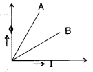
Answer:
Since ϕ = LI
∴ L =
Slope of A is greater than slope of B
∴ Inductor A has larger value of self inductance than inductor B.
Question 2.
Define self-inductance of a coil. Write its S.I. unit. (All India 2010)
Answer:
Self induction is the property of a coil by virtue of which it opposes the growth or decay of the current flowing through it.
S.I. unit of self-inductance is henry (H).
Question 3.
Two bar magnets are quickly moved towards a metallic loop connected across a capacitor ‘C’ as shown in the figure. Predict the polarity of the capacitor. (All India 2013)
Answer:
When both magnets move towards loop, the A side plate of cL capacitor will be positive while the lower plate B is negative, making the induced current in a clockwise direction.

Question 4.
Predict the polarity of the capacitor when the two magnets are quickly moved in the directions marked by arrows.
Answer:
Curerent in the coil will be anti-clockwise, when seen from the left, therefore plate A will become + ve (positive) and plate B will be negative.
Question 5.
Predict the directions of induced currents in metal rings 1 and 2 lying in the same plane where current I in the wire is increasing steadily.
Answer:
In metal ring 1, the induced current flows in the clockwise direction.
In metal ring 2, the induced current flows in the anticlockwise direction.
Question 6.
Predict the direction of induced current in a metal ring when the ring is moved towards a conductor is carrying current I in the direction shown in the figure.
Answer:
Clockwise direction.
Question 7.
Predict the directions of induced current in metal rings 1 and 2 when current I in the wire is steadily decreasing?
Answer:
In metal ring 1, the induced current flows in Anticlockwise direction.
In metal ring 2, the induced current flows in the Clockwise direction.
Question 8.
A bar magnet is moved in the direction indicated by the arrow between two coils PQ and CD. Predict the directions of induced current in each coil. (All India 2012)
Answer:
By Lenz’s law, the ends of both the coils closer to the magnet behave as south pole. Hence the current induced in both the coils will flow clockwise when seen from the magnet side.
Question 9.
State Lenz’s law. (Comptt. All India 2012)
Answer:
Lenz’s law states that “the polarity of induced emf is such that it tends to produce a current, which opposes the change in magnetic flux that induced it”.
Question 10.
Predict the direction of the induced current in the rectangular loop abed as it is moved into the region of a uniform magnetic field 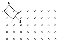
Answer:
The direction of the induced current in the given rectangular loop is anti-clockwise, i.e., cbadc.
Question 11.
State Faraday’s law of electromagnetic induction. (Comptt. All India 2012)
Answer:
Faraday’s law states that “The magnitude of emf induced in a circuit is directly proportional to the rate of change of magnetic flux linked with the circuit”. Mathematically, we can write,
Question 12.
How does the mutual inductance of a pair of coils change when
(i) distance between the coils is increased and
(ii) number of turns in the coils is increased (All India 2013)
Answer:
(i) Mutual inductance decreases’, because flux linked with the secondary coil decreases.
(ii)
Question 13.
A light metal disc on the top of an electromagnet is thrown up as the current is switched on. Why? Give reason. (All India 2013)
Answer:
Because of Eddy Current
If the upper force of the core of the electromagnet acquires north polarity, then according to Lenz’s Law, the lower face of the disc will also acquire north polarity. Due to the force of repulsion between the lower face (N-pole) of the core of the electromagnet, the disc jumps upto a certain height.
Question 14.
The motion of copper plate is damped when it is allowed to oscillate between the two poles of a magnet. What do the cause of this damping? (All India 2013)
Answer:
The cause of this damping is eddy current.
Question 15.
The motion of copper plates is damped when it is allowed to oscillate between the two poles of a magnet. If slots are cut in the plate, how will the damping be affected? (All India 2013)
Answer:
Eddy current will decrease due to which damping reduces.
Question 16.
How does the mutual inductance of a pair of coils change when
(i) distance between the coils is decreased and
(ii) number of turns in the coils is decreased? (All India 2013)
Answer:
(i) increases.
(ii) decreases, because
where [N1 and N2 are number of turns
Question 17.
Predict the polarity of the capacitor in the situation described in the figure. (Comptt. Delhi 2013)
Answer:
When both magnets move towards loop, the A side plate of cL capacitor will be positive while the lower plate B is negative, making the induced current in a clockwise direction.
Question 18.
Two spherical bobs, one metallic and the other of glass, of the same size are allowed to fall freely from the same height above the ground. Which of the two would reach earlier and why? (Delhi 2014)
Answer:
Glass bob would reach earlier because there would be a force acting upward due to eddy currents on metallic bob being conducting, due to earth’s magnetic field. This will slow down the metallic bob.
Question 19.
The electric current flowing in a wire in the direction from B to A is decreasing. Find out the direction of the induced current in the metallic loop kept above the wire as shown. (All India 2014)
Answer:
The direction of current in loop wire will be clockwise.
Question 20.
A conducting loop is held above a current carrying figure. Depict the direction of the current induced in the loop when the current in the wire PQ is constantly increasing. (All India 2014)
Answer:
The current induced is in clockwise direction.
Question 21.
A conducting loop is held below a P current carrying wire PQ as shown. Predict the direction of the induced current in the loop when the current in the wire is constantly increasing. (All India 2014)
Answer:
The current induced is in anti clockwise direction.
Question 22.
A metallic piece gets hot when surrounded by a coil carrying high frequency alternating current. Why? (Comptt. Delhi 2014)
Answer:
Due to the heating effect of eddy currents set up in the metallic piece.
Question 23.
Predict the polarity of the plate A of the capacitor, when a magnet is moved ff’ towards it, as shown in the figure. (Comptt. All India)
Answer:
The plate ’A’ has the positive polarity.
Question 24.
Define the term ‘self-inductance’ of a coil. Write its S.I. Unit. (All India 2015)
Answer:
The self inductance of a coil numerically equals to the induced emf produced in the coil, when the rate of change of current in the coil is unity.![]()
(where L is the self inductance of the coil)
S.I. Unit : Henry.
Question 25.
Name any two applications where eddy currents are used to advantage. (Comptt. Delhi 2015 )
Answer:
Applications of Eddy currents :
- Electromagnetic Damping
- Magnetic Breaking
- Induction Furnace
- Electric Power metres (any two)
Question 26.
A long straight current carrying wire passes normally through the centre of a circular loop. If the current through the wire increases, will there be an induced emf in the. loop? Justify. (Delhi 2015)
Answer:
No,As the magnetic field due to current carrying wire will be in the plane of the circular loop, so magnetic flux will remain zero.
Question 27.
Predict the polarity of the capacitor in the situation described in the given diagram. (All India 2017)
Answer:
The polarity of plate ‘A’ of the given capacitor is positive, while that of plate ‘B’ is negative.
Question 28.
A bar magnet is moved in the direction indicated by the arrow between two coils PQ and CD. Predict the direction of the induced current in each coil (All India 2017)
Answer:
Induced current flows from P to Q through ammeter;
while it flows from D to C through ammeter.
Question 29.
What is the direction of induced currents in metal rings 1 and 2 when current I in the wire is increasing steadily? (All India 2017)
Answer:
The direction of induced current is clockwise in metal ring ‘1’ and anti-clockwise in metal ring ‘2’.
Question 30.
In the figure given, mark the polarity of plates A and B of a capacitor when the magnets are quickly moved towards the coil. (Comptt. All India 2017)
Answer:
The polarity of plate is positive; 1 while that of plate B is negative.
Electromagnetic Induction Class 12 Important Questions Short Answer Type-II
Question 31.
Derive an expression for the self-inductance of a long air-cored solenoid of length l and number of turns N. (Delhi 2008)
Answer:
Consider a long solenoid of length l and radius r with r << 1 and having n turns per unit length. If a current I flows through the coil, then the magnetic field inside the coil is almost constant and is given by
B = µ0nI
Magnetic flux linked with each turn = BA = µ0nIA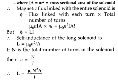
Question 32.
(i) When primary coil P is moved towards secondary coil S (as shown in the figure) the galvanometer shows momentary deflection. What can be done to have larger deflection in the galvanometer with the same battery?
(ii) State the related law. (Delhi 2010)
Answer:
(i) To have larger deflection in the galvanometer with the same battery, coil P has to be moved faster towards S so that rate of change of magnetic flux is more.
(ii) The related law governing this phenomenon is Faraday’s second law of electromagnetic induction which states that induced emf is set up in a circuit when magnetic flux linked with it changes. The magnitude of induced emf is proportional to the rate of change of magnetic flux.
Question 33.
A coil Q is connected to low voltage bulb B and placed near another coil P as shown in the figure. Give reasons to explain the following observations :
(a) The bulb ‘B’ lights.
(b) Bulb gets dimmer if the coil Q is moved towards left. (Delhi 2010)
Answer:
- The bulb B lights on account of emf induced in the coil Q due to mutual induction between P and Q.
- When coil Q is moved towards left, magnetic flux linked with Q decreases and may even reduce to zero at some distance. The emf induced may decrease and the bulb B gets dimmer.
Question 34.
Two identical loops, one of copper and the other of aluminium, are rotated with the same angular speed in the same magnetic field. Compare
(i) the induced emf and
(ii) the current produced in the two coils. Justify your answer.(All India 2010)
Answer:
(i) Induced emf in a coil is ε = NBAω sin ωt
As the angular speed is same, induced emf will also be same in both the loops.
(ii) Current induced in a loop is
As the resistivity of copper is lesser, more amount of current is induced in it.
Question 35.
A rectangular loop and a circular loop are moving out of a uniform magnetic field to a field-free region with a constant velocity ‘v’ as shown in the figure. Explain in which loop do you expect the induced emf to be constant during the passage out of the field region. The magnetic field is normal to the loops. (All India 2010)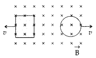
Answer:
In case of rectangular loop, induced emf will be constant. It is because rate of change of the area of rectangular loop is uniform whereas that of a circular loop is not constant.
Question 36.
A current is induced in coil C1 due to the motion of current carrying coil C2.
(a) Write any two ways by which a large deflection can be obtained in the galvanometer G.
(b) Suggest an alternative device to demonstrate the induced current in place of a galvanometer .
Answer:
(a) To obtain a large deflection, one or more of the following steps can be taken :
- Use a rod made of soft iron inside the coil C2.
- Connect the coil to a powerful battery.
- Move the arrangement rapidly towards the test coil C1
(b) Replace the galvanometer by a small torch bulb.
Question 37.
A magnet is quickly moved in the direction indicated by an arrow between two coils C1 and C2 as shown in the figure. What will be the direction of induced current in each coil as seen from the magnet? Justify your answer. (Delhi 2011)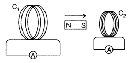
Answer:
When magnet moves in given direction, induced current will be clockwise in both the coils as magnet is going away from C1 and moving towards C2 making C1 as S pole and C2 also as S pole according to Lenz rule. So C1 will try to attract and C2 will try to repel the motion of magnet.
Question 38.
What are eddy currents? Write any two applications of eddy currents. (All India 2011)
Answer:
(a) Eddy current : Due to change in magnetic flux, if there is induced current in the volume (bulk) of the material, it is called as eddy currents. It is a necessary evil in an arrangement as it can be used in applications like electric brakes, induction furnaces and dead-beat galvanometers and brings loss of energy with heat production etc.
(b) (i) As the arm RS of length l is moved with a uniform speed, there is a change in area. It is given by dA = Idx = Ivdt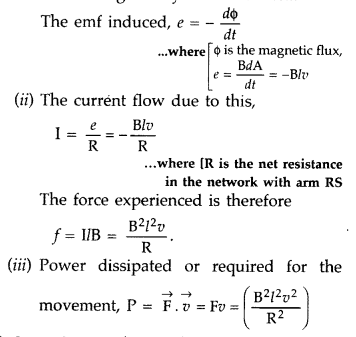
Question 39.
Define self-inductance of a coil. Show that magnetic energy required to build up the current I in a coil of self inductance L is given by –
Answer:
The self-inductance of a coil may be defined as the induced emf set up in the coil due to a unit rate of change of current through it.
Let I be the current through the inductor L at any instant t
The current rises at the rate dlldt, so the induced![]()
Work done against the induced emf in small time dt is![]()
Total work done in building up the current from 0 to I in
This work done is stored as the magnetic field energy U in the inductor![]()
Question 40.
Define mutual inductance between two long coaxial solenoids. Find out the expression for the mutual inductance of inner solenoid of length l having the radius r1 and the number of turns n1 per unit length due to the second outer solenoid of same length and n2 number of turns per unit length. (Delhi 2011)
Answer:
Mutual induction is the phenomenon of inducing emf in a coil due to the rate of change of current in a nearby coil.
When a current I2 is set up through S2 (outer solenoid), it in turn sets up a magnetic flux through S1. Let us denote it by ϕ 1, The corresponding flux linkage with solenoid S1 is,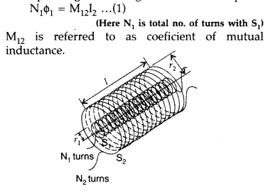
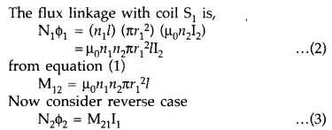
(Here N2 is total no. of turns with S2)
M21 is referred to as coefficient of mutual inductance of solenoid S2 with respect to solenoid S1.
Thus, flux linkage with solenoid S2 is
Using equations (2) and (3), we get
M12 = M21 = M
If a medium of relative permeability (it had been present the mutual inductance would be![]()
Question 41.
A metallic rod of ‘L’ length is rotated with angular frequency of ‘ω’ with one end hinged at the centre and the other end at the circumference of a circular metallic ring of radius L, about an axis passing through the centre and perpendicular to the plane of the ring. A constant and uniform magnetic field B parallel to the axis is present everywhere. Deduce the expression for the emf between the centre and the metallic ring. (Delhi 2012)
Answer:
The magnitude of the emf, generated across a length dr of the rod, as it moves at right angles to the magnetic field, is given by
dε = Bvdr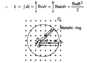
Alternatively, The potential difference across the resistor is equal to the induced emf and equal B x .(rate of change of area of loop), If θ is the angle between the rod and the radius of the circle at P at time t, the area of the sector OPQ (as shown in the figure) is given by![]()
where [R is the radius of the circle]
Question 42.
Derive the expression for the self inductance of a long solenoid of cross sectional area A and. length l, having n turns per unit length.(Delhi 2012)
Answer:
Self-induction of a long solenoid : Consider a long solenoid of length l and radius r with r << 1 and having n turns per unit length. If a current I flows through the coil, then the magnetic field inside the coil is almost constant and is given by![]()
Magnetic flux linked with each turn,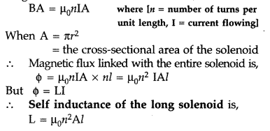
Question 43.
State Lenz’s Law.
A metallic rod held horizontally along east-west direction, is allowed to fall under gravity. Will there be an emf induced at its ends? Justify your answer. (Delhi 2012)
Answer:
Lenz’s law states that “the polarity of induced emf is such that it tends to produce a current, which oppose the change in magnetic flux that induced it”.
Yes there will be an emf induced as the horizontal component of field of earth, velocity of the motion of the rod and the length of the rod are all perpendicular to each other.
The magnetic flux due to vertical component of Earth’s magnetic field keeps on changing as the metallic rod falls down.
Question 44.
A rectangular loop PQMN with movable arm PQ of length 10 cm and resistance 2 Ω is placed in a uniform magnetic field of 0.1 T acting perpendicular to the plane of the loop as is shown in the figure. The resistances of the arms MN, NP and MQ are negligible. Calculate the
(i) emf induced in the arm PQ and
(ii) current induced in the loop when arm PQ is moved with velocity 20 m/s. (Comptt. Delhi 2014)
Answer: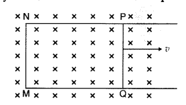
(i) emf induced![]()
(ii) Current in the loop,![]()
Question 45.
A rectangular loop PQMN with movable arm PQ of length 20 cm and resistance 5 Ω is placed in a uniform magnetic field of 0.2 T acting perpendicular to the plane of the loop as is shown in the figure.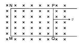
The resistances of the arms MN, NP and MQ are negligible. Calculate the
(i) emf induced in the arm PQ and
(ii) current induced in the loop when arm PQ is moved with velocity 15m/s (Comptt. Delhi 2014)
Answer:
Electromagnetic Induction Class 12 Important Questions Short Answer Type – II SA – II
Question 46.
A metallic rod of length l is rotated at a constant angular speed to, normal to a uniform magnetic field B. Derive an expression for the current induced in the rod, if the resistance of the rod is R. (Delhi 2008)
Answer:
emf produced/induced across a small-section (dr) on the rod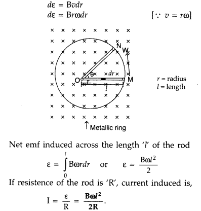
Question 47.
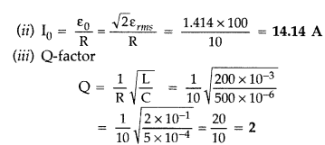
An inductor 200 mH, capacitor 500 µF, resistor 10 Ω are connected in series with a 100 V variable frequency a.c. source. Calculate the
(i) frequency at which the power factor of the circuit is unity
(ii) current amplitude at this frequency
(iii) Q-factor (Delhi 2008)
Answer:
(i) Power factor will be unity at resonance,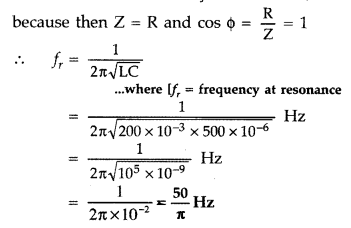
Question 48.
A coil of number of turns N, area A, is rotated at a constant angular speed ω, in a uniform magnetic field B, and connected to a resistor R. Deduce expressions for :
(i) Maximum emf induced in the coil.
(ii) Power dissipation in the coil. (Delhi 2008)
Answer:
We know that induced emf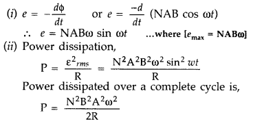
Question 49.
(a) Define self inductance. Write its S.I. units.
(b) Derive an expression for self inductance of a long solenoid of length l, cross-sectional area A having N number of turns. (Delhi 2009)
Answer:
(a) Self-inductance of a coil
Since flux ϕ = LI![]()
where [L is coefficient of self-induction or self inductance]
Self inductance is numerically equal to the magnetic flux linked with the coil when unit current passes through it.
Its S.I. unit is henry.
(b)
Consider a long solenoid of length l and radius r with r << 1 and having n turns per unit length. If a current I flows through the coil, then the magnetic field inside the coil is almost constant and is given by
B = µ0nI
Magnetic flux linked with each turn = BA = µ0nIA
Question 50.
(i) State Faraday’s law of electromagnetic induction.
(ii) A jet plane is travelling towards west at a speed of 1800 km/h. What is the voltage difference developed between the ends of the wing having a span of 25 m, if the Earth’s magnetic field at the location has a magnitude of 5 × 10⁻⁴ T and the dip angle is 30°? (All India)
Answer:
(i) First law : Whenever the magnetic flux linked with a closed circuit changes, an emf (and hence a current) is induced in it which lasts only so long as the change in flux is taking place. This phenomenon is called electromagnetic induction.
Second law : The magnitude of the induced emf is equal to the rate of change of magnetic flux linked with the closed circuit.
Since v, l and B are to be perpendicular to get induce emf, the vertical component alone will contribute to the induction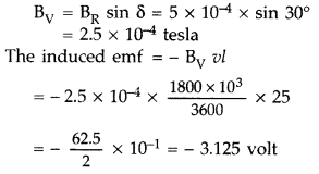
– ve sign signifies that the emf will oppose the change in magnetic flux causing it.
Question 51.
State the law that gives the polarity of the induced emf. (All India 2009)
Answer:
Law that gives the polarity of the induced emf is :
Lenz’s law : “The direction of induced e.m.f. is such that it opposes the cause which produces it. The polarity of induced e.m.f. can be determined by Lenz’s law.”
Question 52.
A metallic rod of length ‘l’ is rotated with a frequency v with one end hinged at the centre and the other end at the circumference of a circular metallic ring of radius r, about an axis passing through the centre and perpendicular to the plane of the ring. A constant uniform magnetic field B parallel to the axis is present every where. Using Lorentz force, explain how emf is induced between the centre and the metallic ring and hence obtain the expression for it. (Delhi 2013)
Answer:
The magnitude of the emf, generated across a length dr of the rod, as it moves at right angles to the magnetic field, is given by
dε = Bvdr
Alternatively, The potential difference across the resistor is equal to the induced emf and equal B x .(rate of change of area of loop), If θ is the angle between the rod and the radius of the circle at P at time t, the area of the sector OPQ (as shown in the figure) is given by![]()
where [R is the radius of the circle]
Question 53.
Starting from the expression for the energy w =
Answer:
From these two equations, we get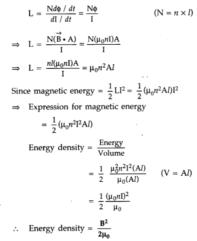
Question 54.
A metallic rod of length ‘l’ is rotated with a uniform angular speed ω, with one end hinged at the centre and the other end at the circumference of a circular metallic ring of radius R = l, about an axis passing through the centre and perpendicular to the plane of the ring. A constant and uniform magnetic field B parallel to the axis is present eveywhere. Deduce the expression for the emf induced in the rod.
If r is the resistance of the rod and the metallic ring has negligible resistance, obtain the expression for the power generated. (Comptt. All India 2013)
Answer:
Are swept per rotation = πR2 = πl2 [∵ R = l]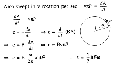
Question 55.
Write its SI unit for self-inductance of a coil. Derive the expression for self-inductance of a long solenoid of cross-sectional area ‘A’, length ‘l’ having ‘n’ turns per unit length. (Comptt. All India 2013)
Answer:
Coefficient of self induction.
Consider a coil L as shown in Figure. Suppose a current I flows through the coil at any instant then magnetic flux ϕ linked with the coil is directly proportional to the current passing through it at that instant.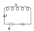
![]()
⇒ ϕ = LI where [L is called coefficient of self induction]
If I = 1, then ϕ = L
Thus, self inductance of a coil is numerically equal to the magnetic flux linked with the coil, when a unit current flows through it.
The SI unit of self inductance is henry (H).
Expression for self-inductance : Consider a long solenoid of length Z and cross-sectional area A having n turns per unit length.
The magnetic field due to a current flowing in the solenoid is B = µ0nl
Total flux linked with the solenoid is,![]()
where [nl is the total number of turns.]
Thus, the self inductance is, 
If we fill the inside of the solenoid with a material of relative permeability µr then
L = µrµ0n2Al
Question 56.
A wheel with 8 metallic spokes each 50 cm long is rotated with a speed of 120 rev/min in a plane normal to the horizontal component of the Earth’s magnetic field. The Earth’s magnetic field at the place is 0.4 G and the angle of dip is 60°. Calculate the emf induced between the axle and the rim of the wheel. How will the value of emf be affected if the number of spokes were increased? (All India 2013)
Answer:
If a rod length ‘l’ rotates with angular speed ω in the uniform magnetic field B,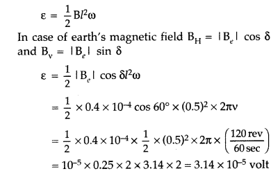
The induced emf will not change with the increase in the number of spokes.
Question 57.
Define the term ‘mutual inductance’ between the two coils.
Obtain the expression for mutual inductance of a pair of long coaxial solenoids each of length l and radii r1 and r2 (r2 >> r1). Total number of turns in the two solenoids are N1 and N2 respectively. (All India 2013)
Answer:
(i) Mutual inductance. The mutual inductance of two coils is numerically equal to the induced emf produced in one coil, when the rate of change of current is unit in the other coil.
(ii)
(a) Lenz’s law (Direction) : “The direction of induced current in a circuit is such as to oppose
the change that causes it. So
When north pole of a magnet, for example, is brought near a coil, then the nearer end of the coil will acquire north polarity and mechanical work will be needed to cause the relative motion between the coil and the magnet. This work, in fact, converts itself in the form of induced emf. Hence, the phenomenon of electromagnetic induction is in accordance with the law of conservation of energy.
(b) When a current I2 is set up through S2, it in turn sets up a magnetic flux through S1. Let us denote it by ϕ1. The corresponding flux linkage with solenoid S1 is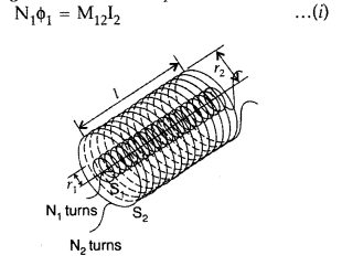
M12 is called the mutual inductance of solenoid S1 with respect to solenoid S2.
The magnetic field due to the current I2 in S2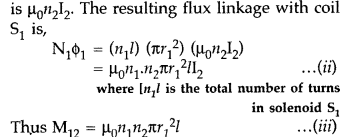
We now consider the reverse case :
A current I1, is passed through the solenoid S1 and the flux linkage with coil S2 is,![]()
M21 is called the mutual inductance of the solenoid S2 with respect to solenoid S1
The flux due to the current I1 in S1 can be assumed to be confined solely inside S1 since the solenoid are very long. Thus, flux linkage with solenoid S2 is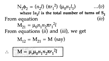
Question 58.
Define the term self-inductance of a solenoid. Obtain the expression for the magnetic energy stored in an inductor of self-inductance L to build up a current I through it. (All India 2014)
Answer:
Self-inductance: emf is induced in a single isolated coil due to change of flux through the coil by means of varying the current through the same coil. This phenomenon is called self-induction. In this case, flux linkage through a coil of N turns is proportional to the current through the coil and is expressed as![]()
where constant of proportionality L is called self-inductance of the coil. It is also called the coefficient of self-induction of the coil. When the current is varied, the flux linked with the coil also changes and an emf is induced in the coil. Using the above equation the induced emf is given by
Thus, the self-induced emf always opposes any change (increase or decrease) of current in the coil. It is possible to calculate the self-inductance for circuits with simple geometries. Let us calculate the self-inductance of a long solenoid of cross-sectional area A and length Z, having n turns per unit length. The magnetic field due to a current I flowing in the solenoid is B = µ0nI (neglecting edge effects, as before). The total flux linked with the solenoid is
If we fill the inside of the solenoid with a material of relative permeability (e.g. soft iron, which has a high value of relative permiability), then L = µrµ0n2Al
The self-inductance of the coil depends on its geometry and on the permeability of the medium. The self-induced emf is also called the back emf as it opposes any change in the current in a circuit. Physically, the self-inductance plays the role of inertia. It is the electromagnetic analogue of mass in mechanics. So, work needs to be done against the back emf (ε) in establishing the current. This work done is stored as magnetic potential energy. For the current I at an instant in a circuit, the rate of work done is![]()
If we ignore the resistive losses and consider only inductive effect, then using![]()
Total amount of work done in establishing the current I is,
Thus, the magnetic energy required to build up the current I is,![]()
Question 59.
(a) A rod of length l is moved horizontally with a uniform velocity ‘v’ in a direction perpendicular to its length through a region in which a uniform magnetic field is acting vertically downward. Derive the expression for the emf induced across the ends of the rod.
(b) How does one understand this motional emf by invoking the Lorentz force acting on the free charge carriers of the conductor? Explain. (All India 2014)
Answer:
(a) Induced emf in rotating metallic rod: Suppose a rectangular loop LMNO is placed in a uniform magnetic field B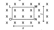
Suppose at any instant, length ON = x
Area of the loop LMNO = lx
Flux through the loop, ϕ = Blx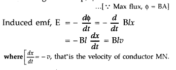
(b) The induced emf produced in a rod (l) moved with velocity (v) kept in a magnetic field (perpendicular to the plane of length of the rod) is given by e = BIv …(i)
This induced emf is called motional emf, by moving a conductor instead of varying the magnetic field; that is by changing the magnetic flux enclosed by the circuit.
We can explain motional emf by invoking the Lorentz force acting on the free charge carriers of the conductor.
Lorentz force acting on charge q is![]()
The work done in moving, the charge through a distance is : W = qvBl
Since the emf is the work done per unit![]()
This expression is the same as given in (i)
Question 60.
Derive the expression for the magnetic energy stored in a solenoid in terms of magnetic field B, area A and length l of the solenoid carrying a steady current I. How does this magnetic energy per unit volume compare with the electrostatic energy density stored in a parallel plate capacitor? (Comptt. Delhi 2015)
Answer:
Magnetic Energy in a Solenoid,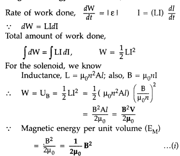
The electrostatic energy stored per unit volume for a parallel plate capacitor,![]()
These two expressions are similiar in nature.
Question 61.
(i) Define mutual inductance.
(ii) A pair of adjacent coils has a mutual inductance of 1.5 H. If the current in one coil changes from 0 to 20 A in 0.5 s, what is the change of flux linkage with the other coil? (Delhi 2015)
Answer:
(i) Mutual inductance : Magnetic flux, linked with the secondary coil due to the unit current flowing in the primary coil,
Therefore, induced emf associated with the secondary coil, for a unit rate of change of current in the primary coil.
[i.e. the phenomenon of production of induced emf in one coil due to change in current in neighbouring coil]
(ii) Given : M = 1.5 H, I1 = 0, I2 = 20 A, ∆t = 0.5 sec, dϕ = ?
Change in flux (dϕ) = MdI = M(I2 – I1) = 1.5 (20 – 0) = 30 Weber
Question 62.
(a) Define self-inductance of a coil and hence write the definition of ‘Henry’.
(b) Write any two factors each on which the following depends :
(i) Self inductance of a coil.
(ii) mutual inductance of a pair of coils. (Comptt. All India 2015)
Answer:
(a) The self-inductance (L) of a coil equal the magnetic flux linked with it, when a unit current flows through it.
One henry is the self inductance of a coil for which the magnetic flux, linked with it, due to a current of 1A, flowing in it, equals one weber.
(b) (i) Self inductance of a coil depends on
- Its geometry (area and length of a coil.
- Number of turns
- Medium within the coil
(ii) Mutual inductance of a given pair of coils depends on
- Their geometries
- Their distance of separation
- Number of turns in each coil.
- Nature of medium in the intervening space.
Question 63.
(a) Define the term ‘self-inductance’ and write its S.I. unit.
(b) Obtain the expression for the mutual inductance of two long co-axial solenoids S1 and S2 wound one over the other, each of length L and radii r1 and r2 and n1 and n2 number of turns per unit length, when a current I is set up in the outer solenoid S2. (Delhi 2017)
Answer:
(a) Self inductance of a coil, equals the magnitude of the efrif induced in it, when the current in the coil, is changing at a unit rate.
S.I. unit : henry
(b) Consider two long solenoids S1 and S2 of same length l such that solenoid S2 surrounds S1 completely.
Let a current I2 flow through S2. This sets up a magnetic flux ϕ1 through each turn of the coil S1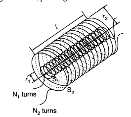
Total flux linked with S1, N1ϕ1 = M12I2… (i)
Where M12 is the mutual inductance between the two solenoids
Magnetic field due to the current I2 and S2 is µ0n2I2
Therefore, resulting flux linked with S1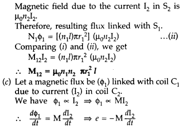
Question 64.
Define mutual inductance between a pair of coils. Derive an expression for the mutual inductance of two long coaxial solenoids of same length wound one over the other. (All India 2017)
Answer:
(a) Mutual inductance of two coils is equal to the magnetic flux linked with one coil when a unit current is passed in the other coil.
Hence, Mutual inductance is equal to the induced emf set up in one coil when the rate of change of current flowing through the other coil is unity.
S.I. unit : Henry, (Weber ampere-1) or (volt second ampere-1)
(b) Consider two long solenoids S1 and S2 of same length l such that solenoid S2 surrounds S1 completely.
Let a current I2 flow through S2. This sets up a magnetic flux ϕ1 through each turn of the coil S1
Total flux linked with S1, N1ϕ1 = M12I2… (i)
Where M12 is the mutual inductance between the two solenoids
Magnetic field due to the current I2 and S2 is µ0n2I2
Therefore, resulting flux linked with S1
Question 65.
Define self-inductance of a coil. Obtain the expression for the energy stored in an inductor L connected across a source of emf. (All India 2017)
Answer:
(i) Definition of self-inductance :
(a) The self-inductance (L) of a coil equal the magnetic flux linked with it, when a unit current flows through it.
One henry is the self inductance of a coil for which the magnetic flux, linked with it, due to a current of 1A, flowing in it, equals one weber.
(ii) Expression for Magnetic Energy density in an ideal inductor : Instantaneous induced emf in an inductor when current changes through it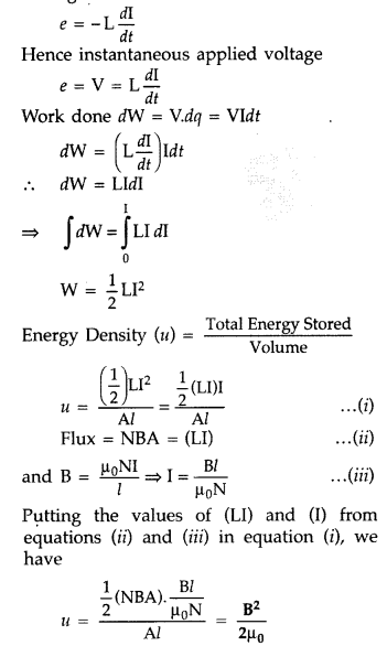
Question 66.
State Lenz’s law. Explain, by giving examples that Lenz’s law is a consequence of conservation of energy. (Comptt. Delhi 2017)
Answer:
Lenz’s law states that “The polarity of induced emf is such that it tends to produce a current which opposes the change in magnetic flux that produced it.”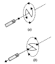
As shown in the diagram (a) given, when the north pole of a bar magnet is pushed towards the close coil, the magnetic flux through the coil increases and the current is induced in the coil in such a direction that it opposes the increase in flux. This is possible when the induced current in the coil is in the anticlockwise direction.
Similarly as shown in the diagram (b), just the opposite happens when the north pole is moved away from the coil.
In either case, it is the work done against the force of magnetic repulsion or attraction that gets ‘converted’ into the induced emf.
Question 67.
The current through two inductors of self-inductance 12 mH and 30 mH is increasing with time at the same rate. Draw graphs showing the variation of the
(a) emf induced with the rate of change of current in each inductor
(b) energy stored in each inductor with the current flowing through it.
Compare the energy stored in the coils, if the power dissipated in the coils is the same. (Comptt. All India 2017)
Answer: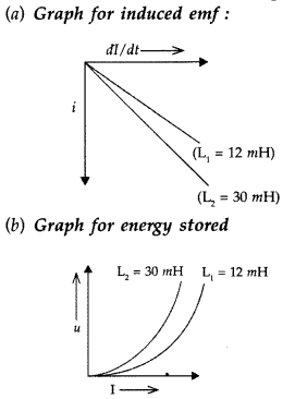
Comparison of energy stored :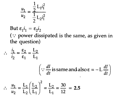
Question 68.
The current through two inductors of self-inductance 15 mH and 25 mH is increasing with time at the same rate. Draw graphs showing the variation of the
(a) emf induced with the rate of change of current
(b) energy stored in each inductor with the current flowing through it.
Compare the energy stored in the coils, if the power dissipated in the coils is the same. (Comptt. All India 2017)
Answer:
Given L1 = 15 mH and L2 = 25 mH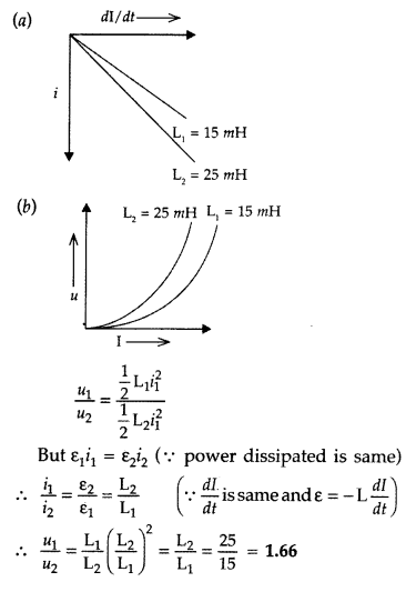
Electromagnetic Induction Class 12 Important Questions Long Answer Type
Question 69.
(a) What are eddy currents? Write their two applications.
(b) Figure shows a rectangular conducting loop PQSR in which arm RS of length ‘l’ is movable. The loop is kept in a uniform magnetic field ‘W directed downward perpendicular to the plane of the loop. The arm RS is moved with a uniform speed ‘v’.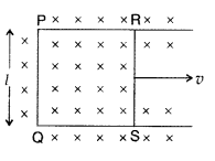
Deduce an expression for
(i) the emf induced across the arm ‘RS’,
(ii) the external force required to move the arm, and
(iii) the power dissipated as heat. (All India 2009)
Answer:
(a) Eddy current : Due to change in magnetic flux, if there is induced current in the volume (bulk) of the material, it is called as eddy currents. It is a necessary evil in an arrangement as it can be used in applications like electric brakes, induction furnaces and dead-beat galvanometers and brings loss of energy with heat production etc.
(b) (i) As the arm RS of length l is moved with a uniform speed, there is a change in area. It is given by dA = Idx = Ivdt
Question 70.
(a) State Lenz’s law. Give one example to illustrate this law. “The Lenz’s law is a consequence of the principle of conservation of energy.” Justify this statement.
(b) Deduce an expression for the mutual inductance of two long coaxial solenoids but having different radii and different number of turns. (All India 2009)
Answer:
(a) Lenz’s law (Direction) : “The direction of induced current in a circuit is such as to oppose
the change that causes it. So
When north pole of a magnet, for example, is brought near a coil, then the nearer end of the coil will acquire north polarity and mechanical work will be needed to cause the relative motion between the coil and the magnet. This work, in fact, converts itself in the form of induced emf. Hence, the phenomenon of electromagnetic induction is in accordance with the law of conservation of energy.
(b) When a current I2 is set up through S2, it in turn sets up a magnetic flux through S1. Let us denote it by ϕ1. The corresponding flux linkage with solenoid S1 is
M12 is called the mutual inductance of solenoid S1 with respect to solenoid S2.
The magnetic field due to the current I2 in S2
We now consider the reverse case :
A current I1, is passed through the solenoid S1 and the flux linkage with coil S2 is,![]()
M21 is called the mutual inductance of the solenoid S2 with respect to solenoid S1
The flux due to the current I1 in S1 can be assumed to be confined solely inside S1 since the solenoid are very long. Thus, flux linkage with solenoid S2 is
Question 71.
State Faraday’s law of electromagnetic induction. Figure shows a rectangular conductor PQRS in which the conductor PQ is free to move in a uniform magnetic field B perpendicular to the plane of the paper. The field extends from x = 0 to x = b and is zero for x > b. Assume that only the arm PQ possesses resistance r.
When the arm PQ is pulled outward from x = 0 to x = 2b and is then moved backward to x = 0 with constant speed v, obtain the expressions for the flux and the induced emf. Sketch the variations of these quantities with distance 0 ≤ x ≤ 2b. (All India 2010)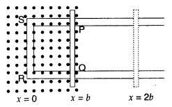
Answer:
Faraday’s law of electromagnetic induction: “The magnitude of the induced emf in a circuit is equal to the time rate of change of magnetic flux through the circuit”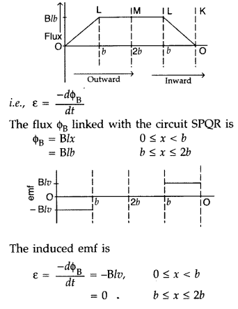
Question 72.
(a) Show that in an a.c. circuit containing a pure inductor, the voltage is ahead of current by π/2 in phase.
(b) A horizontal straight wire of length L extending from east to west is falling with speed v at right angles to the horizontal component of Earth’s magnetic field B.
(i) Write the expression for the instantaneous value of the emf induced in the wire.
(ii) What is the direction of the emf?
(iii) Which end of the wire is at the higher potential? (All India 2011)
Answer:
(a) Average power associated with an inductor.
When a.c. is applied to an ideal inductor,current lags behind the voltage in phase by 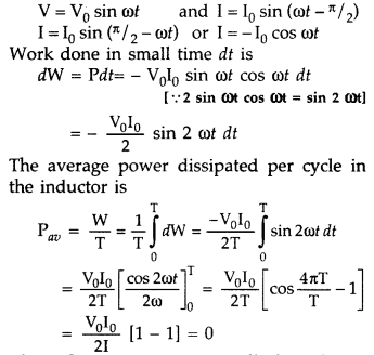
Thus the average power dissipated per cycle in an inductor is zero.
(b) (i) The expression for the instantaneous value of the emf induced in the wire is
ε = Blv
(ii) According to Fleming’s right hand rule, “the direction of emf is from west to east”.
(iii) Eastern end of the wire is at the higher electrical potential.
Question 73.
(a) Starting from the expression for the Lorentz magnetic force acting on the free charge carriers of a conductor moving in a perpendicular magnetic field, obtain the expression for the motional emf induced.
(b) Hence deduce the expressions for the power delivered by the source and the power dissipated as Joule heat. (Comptt. Delhi 2012)
Answer: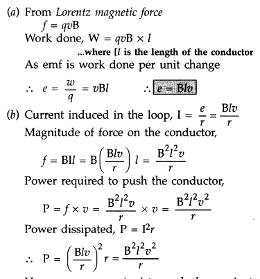
Hence, power required to push the conduct is same as the power dissipated.
Question 74.
(a) Describe a simple experiment (or activity) to show that the polarity of emf induced in . a coil is always such that it tends to produce a current which opposes the change of magnetic flux that produces it.
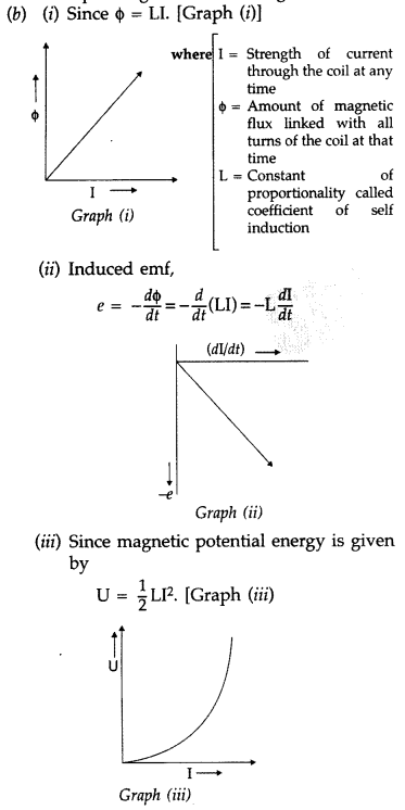
(b) The current flowing through an inductor of self inductance L is continuously increasing. Plot a graph showing the variation of
(i) Magnetic flux versus the current
(ii) Induced emf versus dI/dt
(iii) Magnetic potential energy stored versus the current. (Delhi 2014)
Answer:
(a) Lenz’s law : According to Lenz law, “the polarity of the induced emf is such that it opposes a change in magnetic flux responsible for its production.”
Activity :
When the north pole of a bar magnet is pushed towards the coil, the amount of magnetic flux linked with the coil increases. Current is induced in the coil from a direction such that it opposes the increase in magnetic flux. This is possible only when the current induced in the coil is in anti-clockwise direction, with respect to an observer.
The magnetic movement ➝ M associated with this induced emf has north polarity towards the north pole of the approaching bar magnet.
Similarly, when the north pole of the bar magnet is moved away from the coil, the magnetic flux linked with the coil decreases. To counter this decrease in magnetic flux, current is induced in the coil in clockwise direction so that its south pole faces the receding north pole of the bar magnet. This would result in an attractive force which opposes the motion of the magnet and the corresponding decrease in magnetic flux.
Question 75.
A metallic rod of length l and resistance R is rotated with a frequency v, with one end hinged at the centre and the other end at the circumference of a circular metallic ring of radius l, about an axis passing through the centre and perpendicular to the plane of the ring. A constant and uniform magnetic field B parallel to the axis is present everywhere.
(a) Derive the expression for the induced emf and the current in the rod.
(b) Due to the presence of the current in the rod and of the magnetic field, find the expression for the magnitude and direction of the force acting on this rod.
(c) Hence obtain the expression for the power required to rotate the rod. (Comptt. All India 2012)
Answer: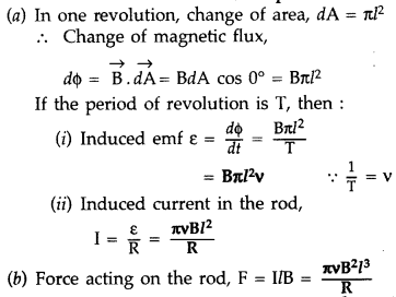
The external force required to rotate the rod opposes the Lorentz force acting on the rod/ external force acts in the direction opposite to the Lorentz force.
Power required to rotate the rod
Question 76.
(a) Define mutual inductance and write its S.I. units.
(b) Derive an expression for the mutual inductance of two long co-axial solenoids of same length wound one over the other.
(c) In an experiment, two coils c1 and c2 are placed close to each other. Find out the expression for the emf induced in the coil ct due to a change in the current through the coil c2. (Delhi)
Answer:
(a) Mutual inductance of two coils is equal to the magnetic flux linked with one coil when a unit current is passed in the other coil.
Hence, Mutual inductance is equal to the induced emf set up in one coil when the rate of change of current flowing through the other coil is unity.
S.I. unit : Henry, (Weber ampere-1) or (volt second ampere-1)
(b) Consider two long solenoids S1 and S2 of same length l such that solenoid S2 surrounds S1 completely.
Let a current I2 flow through S2. This sets up a magnetic flux ϕ1 through each turn of the coil S1
Total flux linked with S1, N1ϕ1 = M12I2… (i)
Where M12 is the mutual inductance between the two solenoids
Magnetic field due to the current I2 and S2 is µ0n2I2
Therefore, resulting flux linked with S1
Question 77.
(a) State Lenz’s law. Use it to predict the polarity of the capacitor in the situation given below :
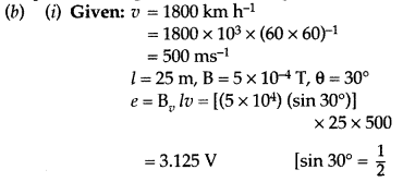
(b) A jet plane is travelling towards west at a speed of 1800 km/h.
(i) Estimate voltage difference developed between the ends of the wing having a span of 25 m if the earth’s magnetic field at the location has a magnitude of 5 × 10⁻⁴ T and dip angle is 30°.
(ii) How will the voltage developed be affected if the jet changes its direction from west to north? (Comptt. All India)
Answer:
(a) Lenz’s law : It states that “the direction of induced emf is such that it tends to produce a current which opposes the change in magnetic flux producing it.”
Polarity of capacitor: Current induced in the coil will oppose the approach of the magnet, therefore, left face of the coil will act as N-pole and right face S-pole. For this the current in coil will be anticlockwise, as seen from left; and hence the plate ‘A’ of the capacitor will be positive and plate ‘B’ will be negative.
(ii) When the jet changes its direction from west to north, the voltage developed will not be affected.
Question 78.
Define mutual inductance of a pair of coils and write on which factors does it depend.
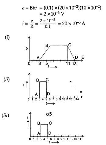
A square loop of side 20 cm is initially kept 30 cm away from a region of uniform magnetic field of 0.1 T as shown in the figure. It is then moved towards the right with a velocity of 10 cm s-1 till it goes out of the field.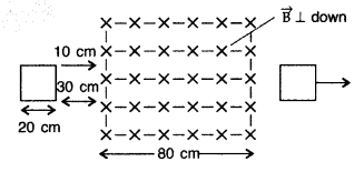
Plot a graph showing the variation of
(i) magnetic flux (ϕ) through the loop with time (t)
(ii) induced emf (ε) in the loop with time t.
(iii) induced current in the loop if it has resistance of 0.1 Ω. (Comptt. All India 2015)
Answer:
(a) Mutual inductance of two coils is equal to the magnetic flux linked with one coil when a unit current is passed in the other coil.
Hence, Mutual inductance is equal to the induced emf set up in one coil when the rate of change of current flowing through the other coil is unity.
S.I. unit : Henry, (Weber ampere-1) or (volt second ampere-1)
Factors:
- Separation between the coils
- Relative orientation of coils
- Number of turns in the coils
Given: Side of square loop (l) = 20 cm = 20 × 10-2 m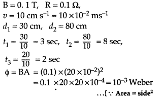
Question 79.
(a) Explain the meaning of the term mutual inductance. Consider two concentric circular coils, one of radius r1 and the other of radius r2 (r1 < r2) placed coaxially with centres coinciding with each other. Obtain the expression for the mutual inductance of the arrangement.
(b) A rectangular coil of area A, having number of turns N is rotated at ‘f revolutions per second in a uniform magnetic field B, the field being perpendicular to the coil. Prove that the maximum emf induced in the coil is 2πf. (All India 2016)
Answer:
(a) Mutual inductance of two coils is equal to the magnetic flux linked with one coil when a unit current is passed in the other coil.
Hence, Mutual inductance is equal to the induced emf set up in one coil when the rate of change of current flowing through the other coil is unity.
S.I. unit : Henry, (Weber ampere-1) or (volt second ampere-1)
(b) Consider two long solenoids S1 and S2 of same length l such that solenoid S2 surrounds S1 completely.
Let a current I2 flow through S2. This sets up a magnetic flux ϕ1 through each turn of the coil S1
Total flux linked with S1, N1ϕ1 = M12I2… (i)
Where M12 is the mutual inductance between the two solenoids
Magnetic field due to the current I2 and S2 is µ0n2I2
Therefore, resulting flux linked with S1
(b) Let N = number of turns in the coil
A = Area of face of each turn
B = Magnitude of the magnetic field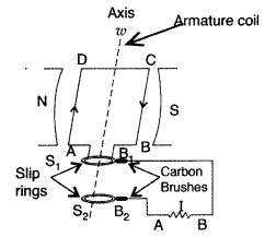
θ = Angle which normal to the coil makes with field 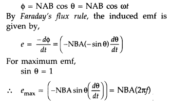
Hence Proved.
Question 80.
(a) A metallic rod of length l is moved perpendicular to its length with velocity v in a magnetic field
(b) A wheel with 15 metallic spokes each 60 cm long, is rotated at 360 rev/min in a place normal to the horizontal component of earth’s magnetic field. The angle of dip at that place is 60°. If the emf induced between rim of the wheel and the axle is 400 mV, calculate the horizontal component of earth’s magnetic field at the place.
How will the induced emf change, if the number of spokes is increased? (Comptt. All India 2016)
Answer:
(a) The magnitude of the emf, generated across a length dr of the rod, as it moves at right angles to the magnetic field, is given by
dε = Bvdr

Alternatively, The potential difference across the resistor is equal to the induced emf and equal B x .(rate of change of area of loop), If θ is the angle between the rod and the radius of the circle at P at time t, the area of the sector OPQ (as shown in the figure) is given by![]()
where [R is the radius of the circle]
(b) Given : Number of spokes (n) = 15,
l = 60 cm = 60 × 10-2 m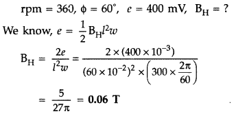
- There would be no effect on induced emf, if number of spokes is increased.


